
You will need to be handy with a soldering iron to install your SKS64, especially if you need to desolder your old kernal ROM chip. If you don't feel comfortable performing this yourself, feel free to contact us. For a minor fee we can perform the surgery for you.
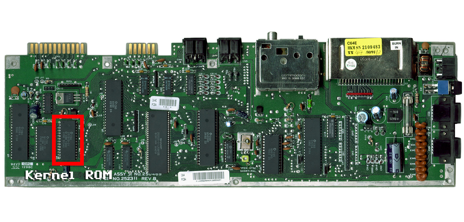
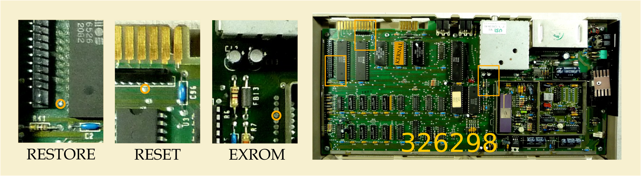
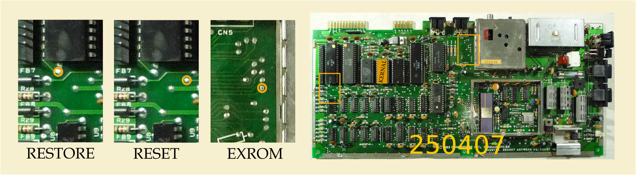
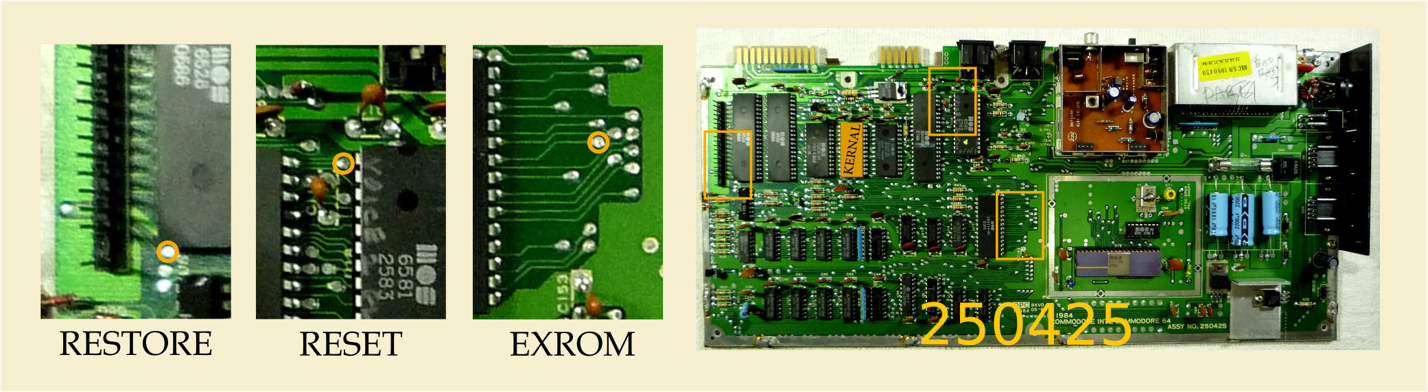
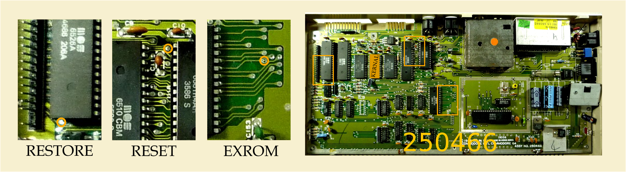
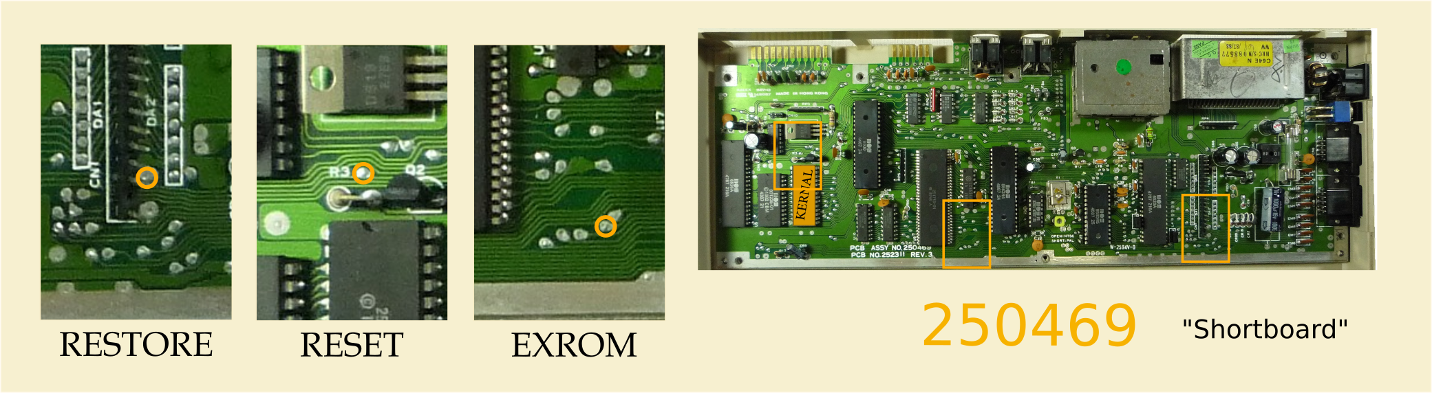
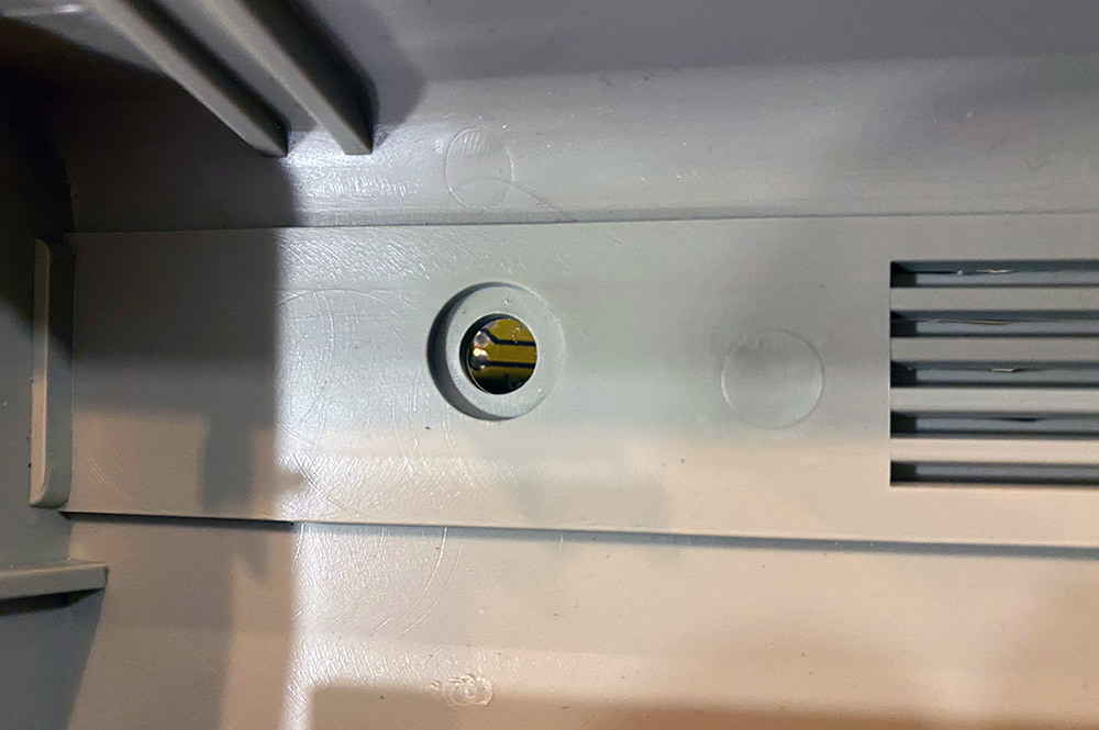
The first step is identifying the location of your kernal ROM. This varies from assembly to assembly. Choose your assembly from the pictures below to locate your kernal.


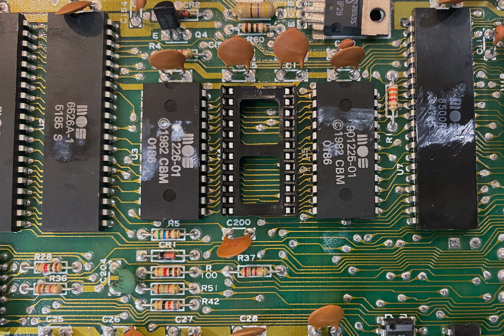
Once you have located your kernal ROM chip, you need to figure out what side of the great Commodore IC socket mystery your machine lies on: Socketed or Not Socketed.
One of the biggest mysteries of the Commodore 64 is why they socketed some chips sometimes and others other times. I have seen machines that have one CIA socketed or one ROM and not the others, ones that have nothing socketed and ones with nearly everything socketed. No rhyme or reason.
If your one of the lucky ones who's kernal ROM is socketed, then you can skip to pulling it out and slotting in the SKS64 but I really do recommend removing the original IC socket if you can. The ones Commodore originally used were terrible and caused all sorts of connectivity issues. Every kit comes with a new dual wipe socket that will be more reliable than the 35+ year old original one.
If your ROM isn't socketed and is soldered onto the motherboard, then you will have to desolder it and solder in the dual wipe socket that is included with our kit.
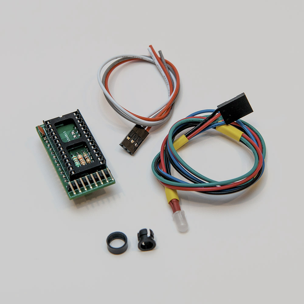
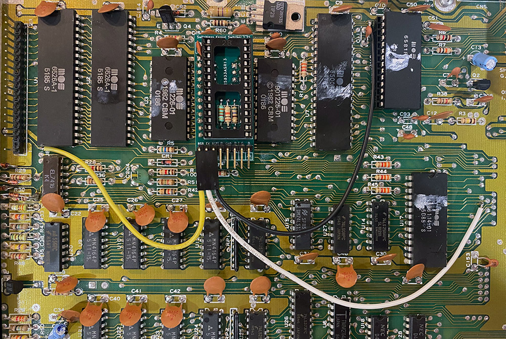
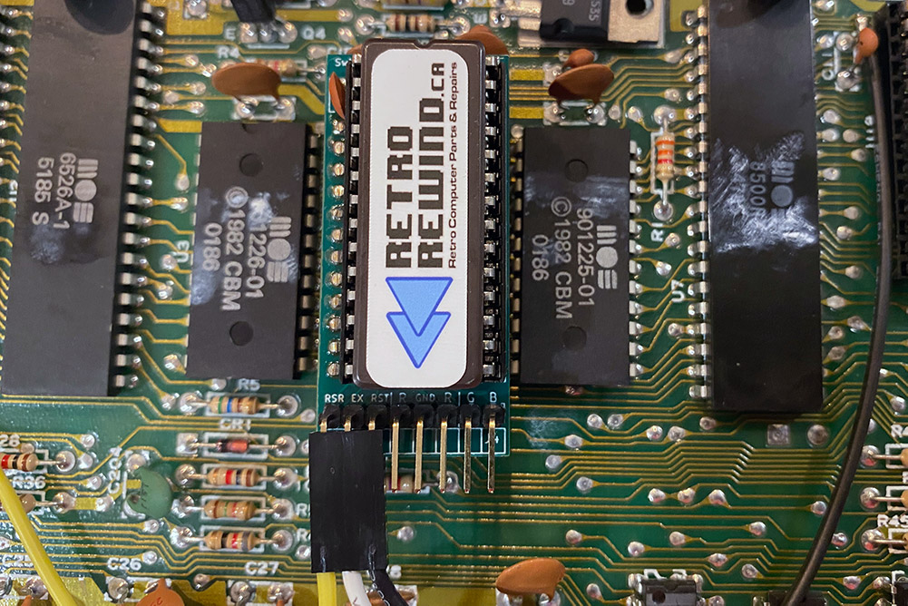
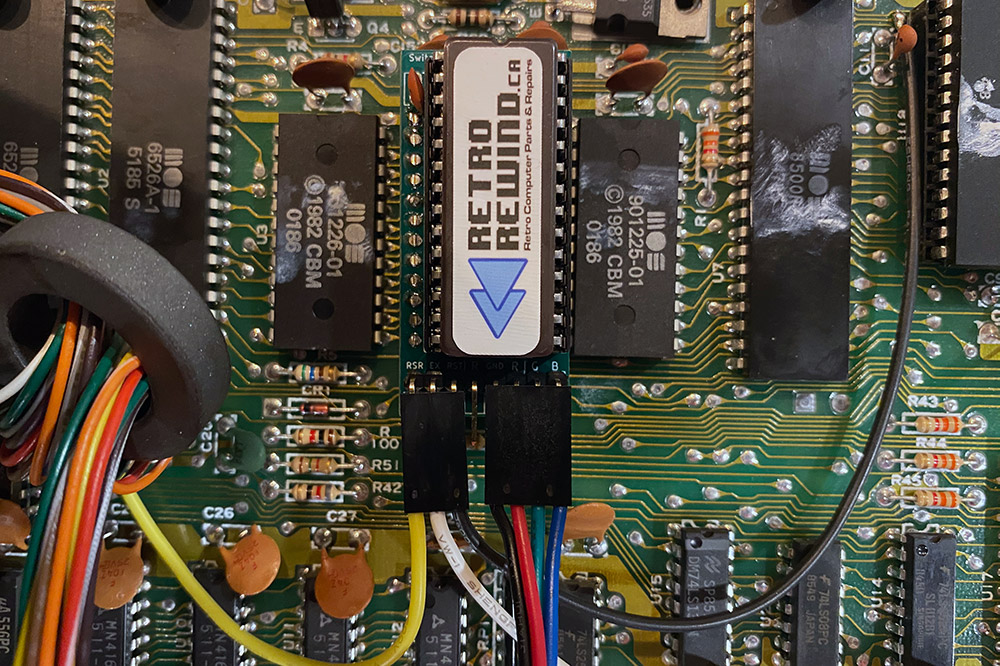
Now that you have freed your C64 of its old kernal ROM and have an empty socket staring at you, its time to slip in your SKS64.
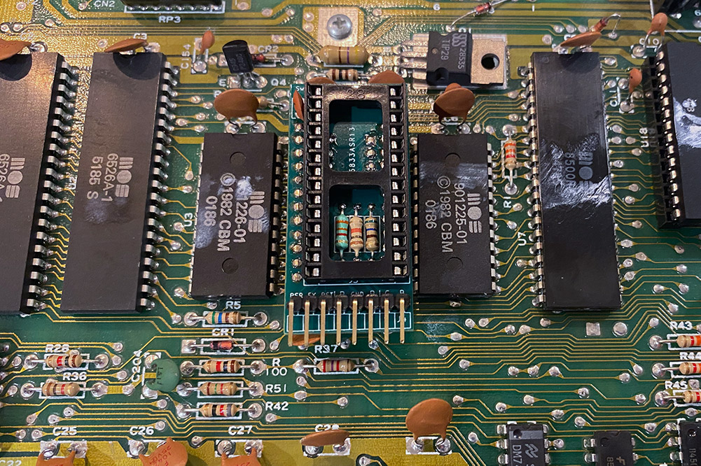
Play close attention to the orientation. The header pins should be facing the front of the 64.
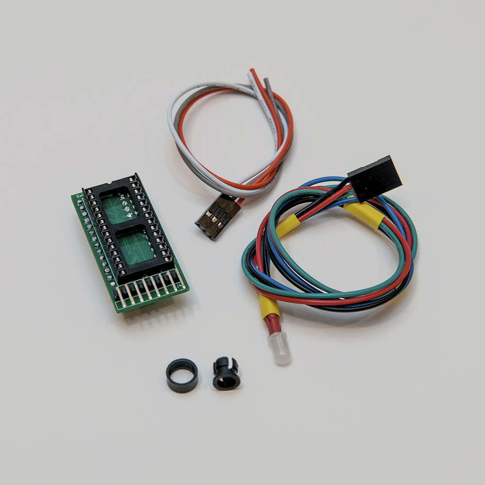
The SKS64 kit comes with a 3 wire harness. Each wire is colour coded and must be connected to the following lines on your 64:
| Wire Colour | Line |
|---|---|
| Yellow | RESTORE |
| White | EXROM |
| Black | RESET |
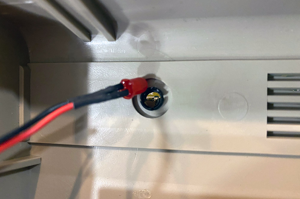
Where the RESTORE, EXROM and RESET lines are located vary by assembly. Choose your assembly from the pictures below to locate the RESTORE, EXROM and RESET lines.
Triple check that you have chosen the correct assembly based on your motherboard and that you have wired everything correctly. Wiring things up wrong can possibly cause irreversible damage to your 64.
Once you have soldered the wiring harness to the RESTORE, EXROM and RESET lines, connect the harness dupont connector to the SKS64 with the Yellow wire (RESTORE) on left side as in the picture below.
The SKS64 comes with a replacement RGB LED and LED holder for your 64. The RGB LED will change to a different colour for each kernal image installed making it real easy to identify which kernal you are using.
Removing the stock LED is easy. Use a pair or needle nose pliers to remove the collar holding the LED in place.
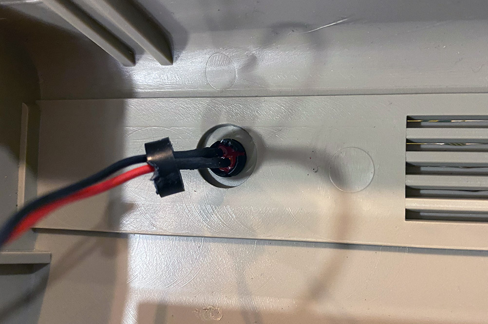
Now push down on the LED with your finger to pop it out of the LED holder.
Push on the LED holder from the inside to pop the LED holder off of the 64 housing.
Slip the new collar over the RGB LED and reverse the steps by snapping in the new LED holder, pushing the RGB LED into the LED holder and snapping the new collar back onto the LED holder to hold it in place.
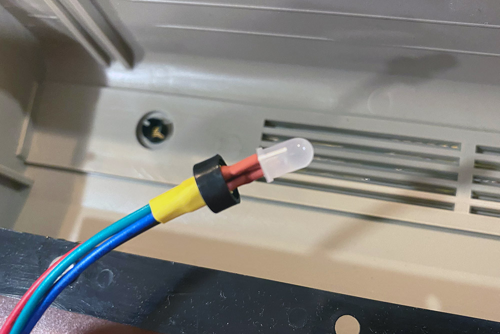
Once you have completed the install, simply connect the RGB LED via its 4 pin dupont connector to the SKS64. The wiring is colour coded to match the pinout on the SKS64 with the black wire being on the left side (GND).
Once you have decided on what kernal images you want to have on your kernal switcher, you will have to concatenate the files into one single bin file that will contain 4 (32k) or 8 (64k) kernal images depending on which EPROM you are using.
You can accomplish this with a simple command line statement.
In Windows, you can use the following approach to combine the kernal images:
In Linux or OS X you would do something like this:
Once you have your combined.bin created, drop your EPROM into your EPROM programmer, fire up its associated software and burn the combined.bin file to it.
Finally, place your 27C256 or 27C512 EPROM into the socket of the SKS64, paying close attention to its orientation: the notch in the EPROM should match the notch in the socket (facing the back of the machine).
You are now in the home stretch. Reconnect your keyboard, connect the RGB LED to the SKS64 and put your machine back together.
Now you are ready to move on to using your new SKS64.
Now that you have the hardware installation out of the way, you need to familiarize yourself with the operation of the SKS64.
Before you can use the SKS64 you must configure it. You need to tell it if you are using a long or shortboard and if you have a 27c256 EPROM which would give you 4 kernal slots or if you have a 27c512 EPROM which would give you 8 kernal slots.
You can enter the SKS64 setup by holding down the RESTORE key while powering on the 64. Continue to hold RESTORE until the LED flashes white. Tap RESTORE to rotate through all the four possible setups. Two flashes, short or long, can be seen periodically. They indicate the selected setup where the first flash is the motherboard form factor, and the second flash is related to the size of the EPROM used.
| Flash Sequence | Configuration |
|---|---|
| LONG - SHORT | Longboard - 4 ROM Banks (27c256) |
| LONG - LONG | Longboard - 8 ROM Banks (27c512) |
| SHORT - SHORT | Shortboard - 4 Banks (27c256) |
| SHORT - LONG | Shortboard - 8 Banks (27c512) |
Once you have chosen your configuration, hold RESTORE again for five seconds to store the setup in the SKS64, and the main program starts.
The selection mode is entered by holding down RESTORE for two seconds, and is indicated with a slight flash of RED on the RGB LED. Quickly, continue to tap RESTORE until the desired colour on the LED is shown. Once you have chosen which ROM you want to use, wait two seconds and the computers resets to the specified kernal.
To perform a soft reset, hold down the RESTORE key for two seconds. After the LED flashes, wait two seconds and a soft reset will be preformed.
For a full reset, hold the RESTORE key for five seconds.
The SKS64 was designed by BWACK under the CERN Open Hardware License v1.2 http://www.ohwr.org/
The full project including original documentation, code and Eagle CAD files are available on GitHub: https://github.com/bwack/C64-Switchless-Multi-Kernal-27C256-adapter
|